Guidelines to basic electrical wiring in your home and similar locations
Electrical wiring and symbols
Electrical symbols are used on home electrical wiring plans in order to show the location, control point(s), and type of electrical devices required at those locations. These symbols, which are drawn on top of the floor plan, show lighting outlets, receptacle outlets, special purpose outlets, fan outlets and switches
Dashed lines are drawn between the symbols to denote which switches control specific lights or receptacles. There are quite a few symbols used to represent the devices used in home electrical wiring but some of them are very similar
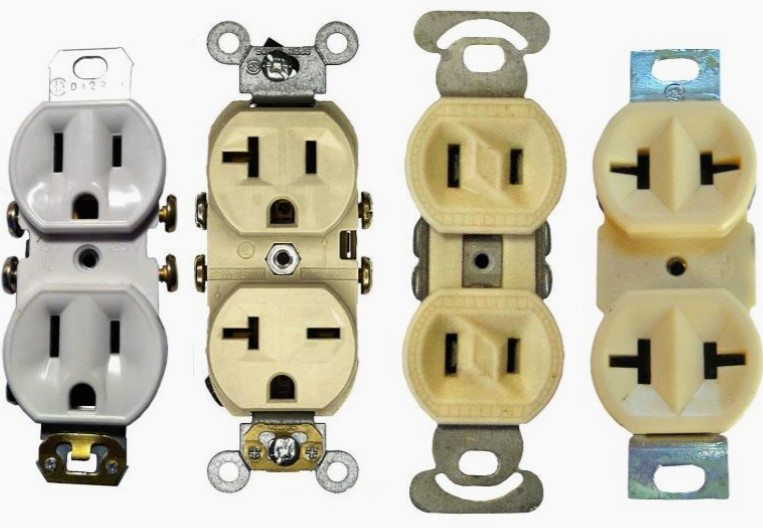
An “outlet” is any point in an electrical system where current is taken out of the system in order to supply power to the attached electrical equipment. An outlet can be one of two basic types: A “Receptacle” outlet or a “Lighting” outlet.
A receptacle outlet is one in which one or more receptacles are installed for the purpose of attaching “plug and cord-connected” type devices, and a lighting outlet is one intended for a direct-wired connection to a lamp holder, luminaire (lighting fixture) or ceiling fan.
How electricity travels throughout the home?
Electricity is supplied to your home through your electric utility’s overhead or buried power lines. Before entering your home, electricity passes through a watt-hour meter which measures the amount of electricity used.
LEARN THE BASICS OF HOME ELECTRICAL WIRING
Electrical wiring can be tricky—especially for the novice. That’s why it’s usually best to hire a professional for anything other than a simple job. Otherwise, you could risk injury, damage or fire. If you do plan to complete a DIY project that has an electrical component, there are some basic things to know about wiring installation.
Understanding electrical wiring
Since the 1940s, any house built (or any older home that has been rewired) has had to follow an electrical code: the NEC—written with safety in mind. NEC code identifies types of electrical wires and electrical cable types by color. When you remove a switch plate, you’ve probably noticed yellow, white, black, red or green wires. They are not there to be decorative; each serves a specific purpose, and some don’t play nicely with others.
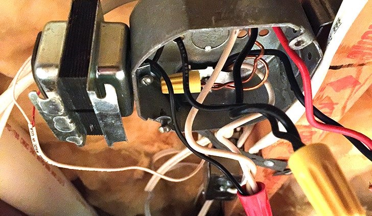
How to Connect electrical wires
When you’re doing wiring installation, you need to identify the parts of the wiring cable, the non-metallic electrical cable: the outer sheathing (the jacket) and the inner wires. The colored “wire” you see—the green, black, red, blue or white—is actually the sheathing that covers the inner copper wires. If you look closely, you’ll see markings stamped on the sheathing to let you know the number and gauge of wires inside. The color of the sheathing lets you know what each wire does.
The following is sort of an electrical wire types chart:
Black wires or “hot wires” carry live electrical loads from the electrical service panel to an outlet, light or other destination.
Red wires are also hot wires used to interconnect smoke detectors, so that if one alarm goes off, all the others do as well.
White and gray wires are neutral wires that connect to the neutral bus bar, which attracts current and carries it throughout the house. Don’t let the “neutral” part fool you because they can still carry a charge—especially if the current load is not balanced.
White wires wrapped in black or red electrical tape are also hot wires. The tape just lets you know that the white wire, which is normally neutral, is being used as a hot wire instead.
Green wires connect the grounding terminal in an outlet box and run it to a ground bus bar in the electrical panel, giving current a place to escape to the ground in the event a live wire touches metal or another conductor. Green wires can only connect to other green wires but can still be live if the electrical system is faulty.
Bare copper wires are the most common type of grounding wires.
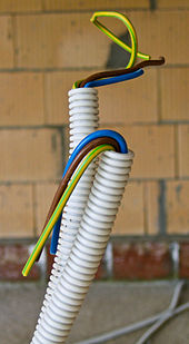
Blue and yellow wires, although not usually found in non-metallic (NM) cable, are sometimes used as hot wires in an electrical conduit. The blue ones are travelers that might be in the switches at both the top and bottom of a staircase to control the same light.
What type of wire is used for residential?
Most modern homes use nonmetallic (NM) cable that consists of two or more wires wrapped inside the colored sheathing mentioned previously. The package of wires usually contains one or more hot wires plus a neutral and a ground. To accommodate wiring in an older home or if your wiring just needs work, you can splice the old wires with new NM cable using a junction box that protects wire connections. The larger circuit wires carry circuit voltage that can be really dangerous to touch. If you don’t know what kind of wires you have, consider them all to be dangerous.
How to Rough-In Electrical Wiring
You can save a lot of money by doing your own wiring. Here we’ll show you to wire an entire room. Even if you’ve never picked up an electrical tool in your life, you can safely rough-in wiring by following the directions in this article. You’ll learn all of the pro techniques for a wiring job, including choosing the right size receptacle boxes, running cable throughout the room, and making the electrical connections.
Tools Required
Drill/driver – cordless
Hammer
Tape measure
Plastic boxes and flexible nonmetallic cable (commonly called Romex) put electrical wiring projects within the skill range of every dedicated DIYer. In this article, we’ll show you some house wiring basics—how to position outlet and switch boxes and run the electrical cable between them. We won’t cover many other house wiring details. For help with circuit design and making connections to your main electrical panel, we recommend you consult a licensed electrician.
Electrical house wiring mistakes can be deadly, so make sure you obtain a permit from your local building department and have an electrical rough-in inspection scheduled with a building official when you’re finished. Draw a sketch of your room that shows lighting, switch and outlet locations. Review your plan with the inspector and ask whether there are any special requirements.
Mark the Box Locations
Measure and mark the center of each box.
Mark the height from the floor to the center of the boxes (usually 48 in. for switches and 12 in. for outlets) or line them up with existing boxes to determine electrical outlet height.
Use letters and symbols to identify boxes.
Add 2×4 blocks to position boxes away from wide window and door trim
Basic Residential Electrical Wiring Rough In and Codes Guide
What are the basic residential wiring circuits? Can you put the hall plug on the same breaker as the dining room? How many switches have to be in the stairwell? What size wire do you use for a dryer? How many amps can 12-2-WG take? All of these questions are answered somewhere in the 700 (more or less) pages of the National Electric Code. Luckily many of the most common residential wiring questions are answered right here on just a couple of pages.
Are You Qualified?
This article is not intended to be a complete guide on the subject of residential wiring, but only an aid to those who already have some knowledge on the subject. I am not encouraging people with little or no experience to tackle a large wiring project (like wiring an entire house), and if that is your intent, then this is just the beginning of the information that you will need to safely and effectively accomplish such a task. There are many excellent guides available in print if you need more information.
Disclaimer: Incompetent or improper wiring work can result in loss of life limb and property. Wiring which is not properly inspected may void your homeowners insurance. In some areas it is not legal for anyone other than a licensed electrician to do wiring work at all. I am not a codes official. I am also not an expert on electrical wiring. I’m just a guy with some practical experience building and wiring houses. Furthermore, the code changes on a regular basis and is subject to local jurisdictions. If you are going to do electrical wiring, you should become educated about the code as it applies in your area.
Service Equipment
The Service equipment (main panel, entrance conductors, meter base, and associated hardware) must be adequate to safely supply the required load. If you haven’t already done so, you can use my Free Load Calculator to determine the size that you will need.
The main service equipment panel shall be mounted either outside or inside the dwelling at the point of entrance of the service conductors to the building. All service equipment and electrical panels shall have a clear area 30″ wide and 36″ deep in front. This clear area must extend from floor to ceiling with no intrusions from other equipment, cabinets, counters, appliances, pipes, etc. Panels are NOT allowed in clothes closets or bathrooms.
Wiring a House
Wiring a house or a basement in a house is something many do-it-yourselfers can tackle. It does require some basic electrical understanding and knowledge of electrical codes but if you have a little of this background you can make it happen. This website is intended to give some guidance for your wiring projects starting with the topics listed below. The frequently asked questions section is also a nice resource for some of the more common DIY electrical questions.
Wire 3 way Switches and other Wiring Diagrams
Below are some of the most common wiring diagrams you will encounter in your home for outlets, switches, and major appliances. Wiring 3 way switches seems to be the most popular topic so I’ve included lots of diagrams for those. Three-way switches allow you to control lights or receptacles from two points. These are commonly used for lighting in a stairway where you want a switch on each floor entering the stairway. Three-way switches are also common in hallways, garages, and kitchens.
Four-way switches are very similar in design to three-ways and are used to control lights or receptacles from three or more switch locations.
AWG stands for “American Wire Gauge” and is a standardized wire gauge system used in the US since 1857 for diameters of round, nonferrous, electrically conducting wire. The cross-sectional area of a wire determines it’s resistance and current-carrying capacity. The large the wire diameter, the less resistance it has to the flow of electrons, and the more current it can carry without overheating